Electronic equipment now suppose most OP Amp using symmetric system power supplies. In a variety of construction electronics module, to connect the module to a power supply that has been filtered to eliminate noise. This design is ideal for this. Voltage regulator power supply is different can also be used to provide symmetric voltage (+ / -) 9 volt, or (+ / -) 12 volts, or (+ / -) 15 volt or (+ / -) 18 volts, can be adapted to another use of voltage regulators using IC 78XX, to 79XX voltage regulator for positive and minus voltage, note the source voltage applied to the input IC regulator should be adjusted.
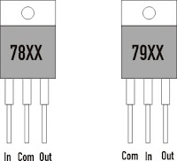
Before installing AC power supply after a rectifier and filtering capacitor DIODE so remember not to put inverted pin IC LM 78XX feet. 78XX series usually provides a positive voltage and a negative voltage 79XX provide. IC legs sequences differ between 78 and 79.
Look at the picture guide below.
(Image 78XX and 79XX)
Note :
A. 78XX
1: Input
2: Com
3: Output
B. 79XX
2: Input
1: Com
3: Output
Look at the picture guide below.
(Image 78XX and 79XX)
 |
| Symmetric + / - 15 Volt Power Supply |
A. 78XX
1: Input
2: Com
3: Output
B. 79XX
2: Input
1: Com
3: Output
NOTE
For you beginners in the field of electronics please be careful in connecting the device to the electrical power supply. Use isolate on the primary transformer before connecting to the mains at home or your school. Please attention to teachers supervising students on the practice. Thank you.Schematic Diagram
 |
| Symmetric + / - 15 Volt Power Supply |
 |
| Symmetric + / - 15 Volt Power Supply |
7815
1: Input
2: Com
3: Output
7915
2: Input
1: Com
3: Output
This circuit is as basic as it gets. Incoming AC voltage is rectified by the diode, then filtered by capacitors and electrolytic capacitors and will be a DC voltage, the positive and negative voltage regulators. After a DC current, diode cathode (+) into a positive regulator for 7815 and 7915 for negative voltage.
To determine whether the two poles of polarity has been working well, my place in the scheme of LED's and associated resistors between each output and 0 volts (ground) line. Capacitors are placed close to the input and output pins of the regulator to increase the stability of the response
Two additional diodes per regulator protects the regulator from short circuiting. To limit the maximum current is better to use a heat sink on the IC LM 78XX to reduce heat.
I use to practice this circuit using standard PCB factory has been punching holes to plug in a few mill-meter leg component, we connect pin legs live components with copper wire (wire power cord). You must know the symbols in the electronic equipment for easy assembly.
0 comments:
Post a Comment